I've compiled all the information I gathered while designing and building this DIY handheld game console, so anyone can build it. This step-by-step guide also explains the choices I made, and the options I decided not to include.
Contents
About this guide | Philosophy | Affordability | Materials | Wiring diagram (step 3.2) | License | References | Comments section
About this guide
This project is not recommended for beginners, as it requires some experience in programming, soldering, 3D printing, and electronics in general. Although this guide has all the steps with maximum detail, expect some tinkering and problem-solving on your part. Not everything will work on the first try. "Hardware is hard."
Feel free to question anything that doesn't make sense to you, as I'm not an expert in any of these topics and built this project to learn. Also, be sure to check the references for more detailed documentation and the license if you plan to build it yourself.
As a recommendation, read the entire guide and watch the video first. This will give you an idea of what the process looks like and what your alternatives are.
If you want to see more projects like this, consider subscribing to my YouTube channel.
Philosophy
I wanted the person building this console to be able to play games as early as the first step. I structured this project in a way that you'll have a functional game console from day one and add improvements in layers whenever you can afford to work on it.
For example, I started playing games with just the Raspberry Pi connected to my PC monitor, an old keyboard, and a phone charger to power it. Later, I added a portable screen, then buttons, then a battery. And I was always able to play games regardless of which step of the process I was in.
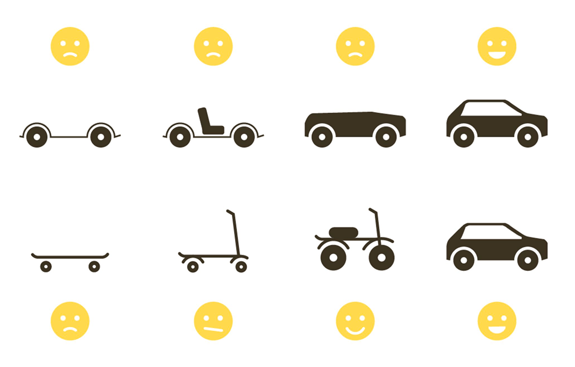
b) DIY project you can enjoy while building it. The features are improvements added over time.
I believe building your own things make you enjoy them the most. And, using them with no need to wait until you finish building them, can make the process even more enjoyable.
There is a chance that you have to buy only few materials to start playing games. The subsequent improvements will be upgrading those areas one by one, taking your time and spending money only when you can. That's exactly how I built mine.
Affordability
Even though I understand that not everyone can access the components that I've used for this build, you'll find that most of the decisions I made are ultimately defined by having more than one option available. For example, you can use a 10 years-old Raspberry Pi that you might have laying around collecting dust or buy one for cheap (they all have the same footprint).
Same applies to 3D printing. You can use the most affordable and compact printers available, as the case can be printed on beds as small as 18 x 18 x 18 cm using basic materials like PLA. Another option is to visit a local makerspace or use a nearby printing service.
I have plans, though, of building the same console but using the ultimate top-of-the-line components like an x86-based SBC capable of running SteamOS (like Latte Panda or anything with an AMD Ryzen embedded APU), an AMOLED screen, and a body carved from a single piece of aluminum.
Materials
I hope you've read the philosophy behind this project first and understand that you don't need to spend money in buying all the components at once. You can enjoy the console since day one with components that you potentially may have at home already.
Before purchasing any components, read the entire guide and watch the video. This will give you an idea of what the process looks like and what your alternatives are.
These are the materials for the exact same final version I built. All of the listed items contain affiliate links. This means that without any cost to you, I might receive a small commision for sales:
-
Raspberry Pi 4 Model B, 4GB RAM. Consider the following:
- Any Raspberry Pi 1B, 2B, 3B, or 4 is suitable.
- For most emulation use cases, 4GB of RAM is more than enough. 8GB won't noticeably improve performance.
- Raspberry Pi Zero, Zero W, and Zero 2W are suitable for this project as well. Though, you'll need to tinker a bit to acommodate the components inside the case.
- If considering using a Raspberry Pi 5, be aware:
- RetroPie supports the Raspberry Pi 5, but with some caveats.
- The Raspberry Pi 5 has significantly higher power requirements. I'm unsure if the PiSugar can meet those needs.
- I haven't yet tested all components and libraries with the RPi 5.
-
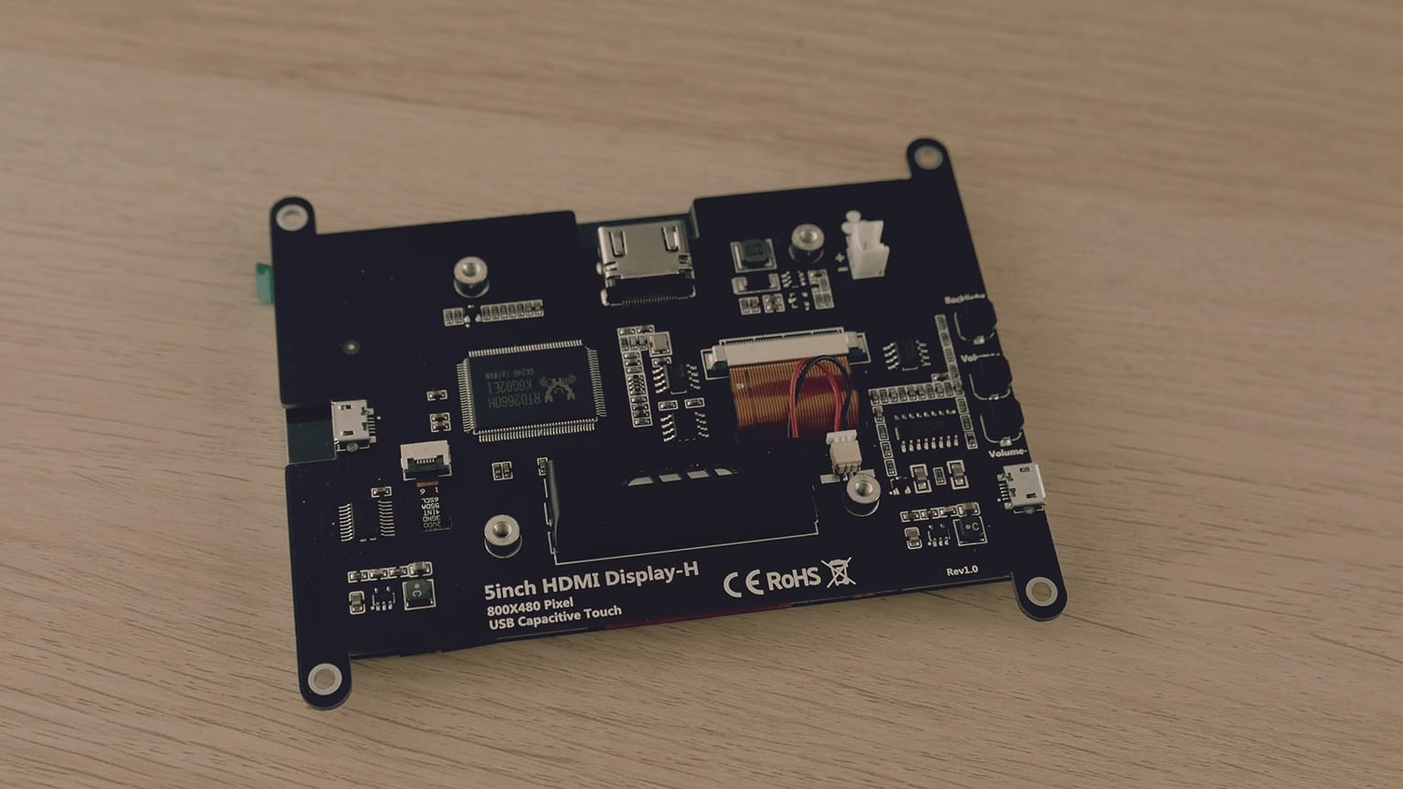
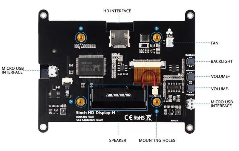
5-inches 800x480 IPS Screen with integrated speaker. Consider the following:
- Any screen of any size and resolution will work.
- However, I can only guarantee that the display linked here will fit physically in the case I designed.
- This project requires you to modify the display linked here, which will definitely void its warranty, so proceed at your own risk.
-
PiSugar 2 Pro. Consider the following:
- Any UPS HAT with a battery compatible with your Raspberry Pi model should work.
- However, I can only guarantee that the UPS and battery linked here will fit physically in the case I designed.
- I'm unsure if other PiSugar models, such as the 2 Plus, S Plus, or 3 Plus, have the same dimensions or not.
- The only thing you need for a proper fit is a battery with max dimensions of 56 x 66 x 10mm (2.2 x 2.6 x 0.4 in).
- I'm unsure if any PiSugar models support the significantly higher power requirements of the Raspberry Pi 5.
- This project requires you to modify your PiSugar, which will definitely void its warranty, so proceed at your own risk.
-
Soft Tactile 8mm Buttons (10 units). Consider the following:
- Those are squishy and feel more like a gamepad, but they aren't essential.
- Any standard tactile button will work just fine.
- Another good option is these Soft Silicone 6mm Push-Buttons.
- 90-Degree Angled Tactile Push Buttons (4 units).
- SD Card. Any SD card on this compatibility list is suitable.
- Breadboard to prototype a gamepad with the push buttons. It will also be useful for any future electronic project you might have.
- Male-to-Female Jumper Wires. Sometimes you can get them bundled with the breadboard.
- 40-Pins (2x20) Female GPIO Header (1 unit) to convert the PiSugar into a top-mounted HAT. Look for solderless headers if you want to minimize the amount of soldering.
-
M2.5 Screws and M2.5 Male-to-Female Standoff Spacers.
- They are often sold together and can be used on a variety of electronic projects.
- The lenghts will depend on your specific build.
- For the inside components, I used two 10mm spacers and four 10mm screws.
- For the enclosure, I used two 16mm and two 20mm screws.
- Metal Heatsink or any type of cooling for Raspberry Pi that can co-exist with a HAT.
01. CPU
In order to run games or, like in my case, emulators the main thing needed is any kind of computer. Since I wanted this to be a DIY handheld game console, my main priority was to get a small yet powerful computer. That's why I chose to work with a Single Board Computer (SBC). I've used one of them before to build an arcade cabinet so I know that SBCs can run games smoothly.
A single-board computer is a complete computer built on a single circuit board, with microprocessor, memory, input/output and other features required of a functional computer.
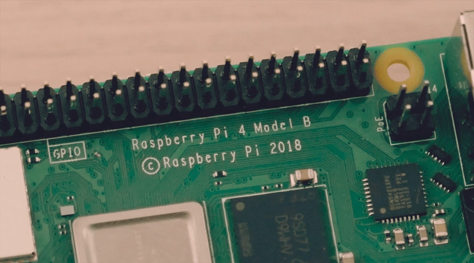
There are plenty of options in the market for SBCs. In my case I went for a Raspberry Pi 4 Model B. Note that at the time of building the console the model 4 was the latest on the market.
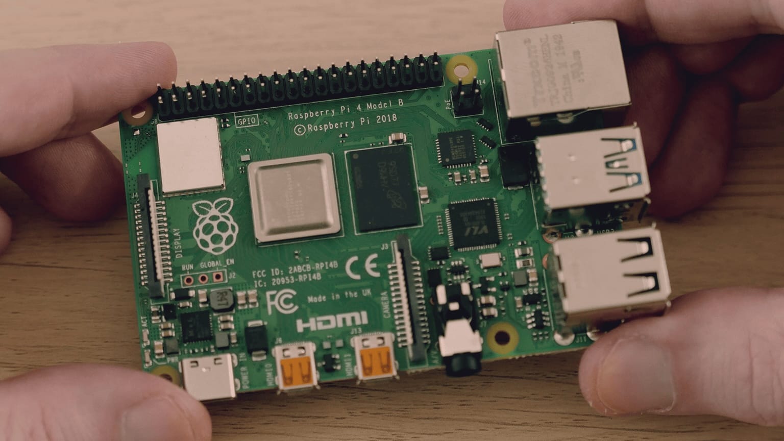
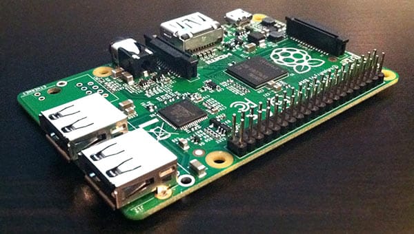
I like the Raspberry Pi for many reasons: it has a massive community, meaning that if you have a problem it is most likely that someone already found a solution for it. Also, all the models have the exact same footprint, meaning that you can build a project using a board from 2012 up until the most recent one, and the physical constraints to build a case around it are gonna be the same. This also makes it even more budget friendly.
Other option that I think it was worth it considering was the Orange Pi 5, but it has a completely different footprint, and also it's too expensive.
Operating Systems
I tried different projects that turn the Pi into an emulation powerhouse. The main 3 were Lakka, RetroPie and Recalbox. In my opinion, RetroPie is the most beginner friendly and it has a massive community behind. Feel free to explore the other ones by yourself if you're interested.
Overclocking
I covered this topic in another blog post about setting up RetroPie. In my opinion, only overclock it if you have an old Raspberry Pi model and you want to run very specific games. Also, keep in mind that doing it the wrong way voids the warranty, so do it the right way as I described here.
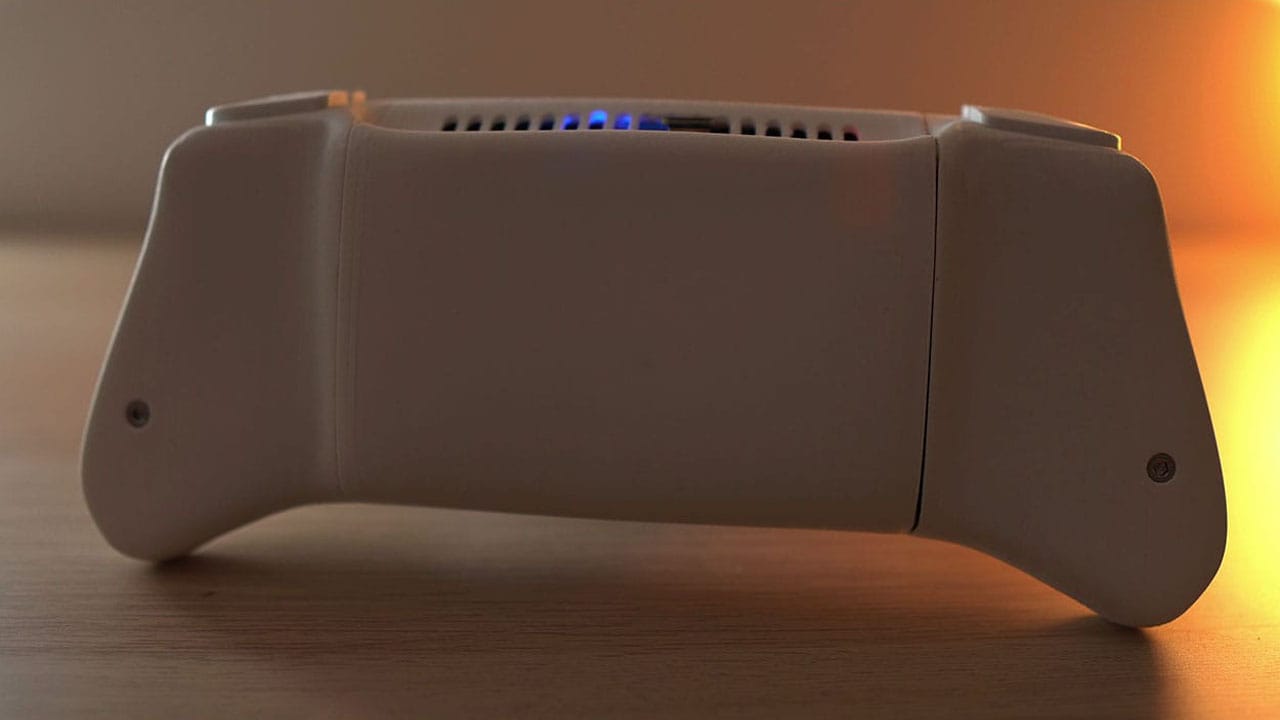
The trade off on a Raspberry Pi handheld game console is being conscious about heat dissipation. I added passive and active cooling to the case in case I wanted to overclock the Raspberry Pi, but I think it was unnecessary.
Slimming down
At some point, my idea was to slim down the Raspberry Pi board to save some space. The idea of slimming down the board is simple: get rid of the tallest ports. The thing is, it would've been an interesting-to-watch video but I would force people to follow the exact same process to build the console.
Compute Module
Another option would've been to use the Raspberry Pi Compute Module (CM3 or CM4) which features the same components of a normal Pi but in a reduced space.
The main con was that I've never worked with it. I wanted to make this first iteration of the console with the things that I know the most, and then I could make it slimmer and faster adding another layer of enhacement.
Also, using the Compute Module would narrow down the options people have to build this console. I guess it's way more people who have a Pi laying around than those who have a CM.
Step 1. Install RetroPie on a Raspberry Pi.
- Identify which model of Raspberry Pi you have.
- Connect a compatible SD card to your computer.
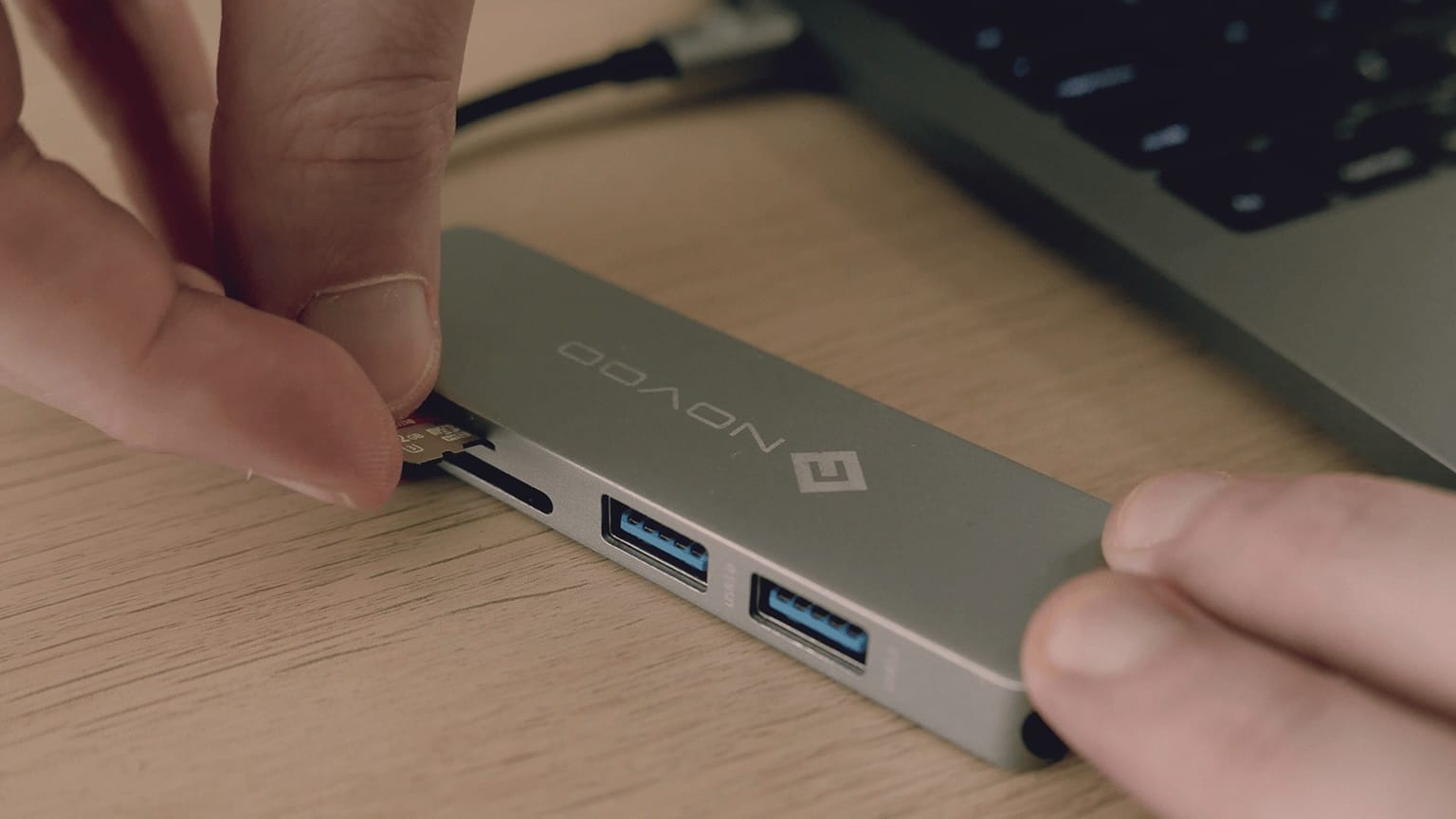
- Download and install the official Raspberry Pi Imager.
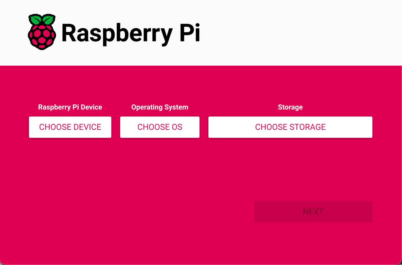
- On the Raspberry Pi Imager, click Choose device and select your Raspberry Pi model.

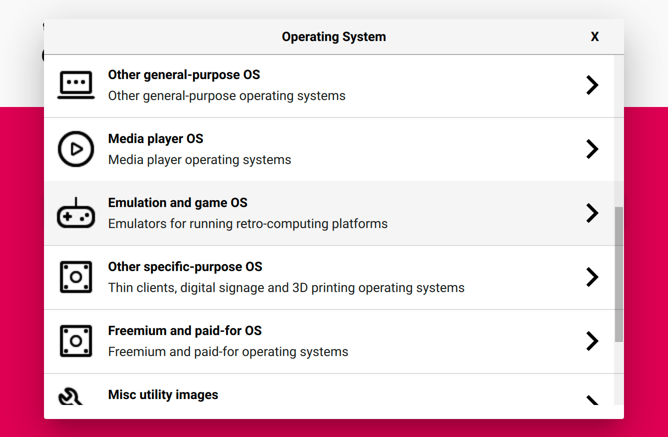
- Click Choose OS. Select "Emulation and game OS", then "RetroPie".
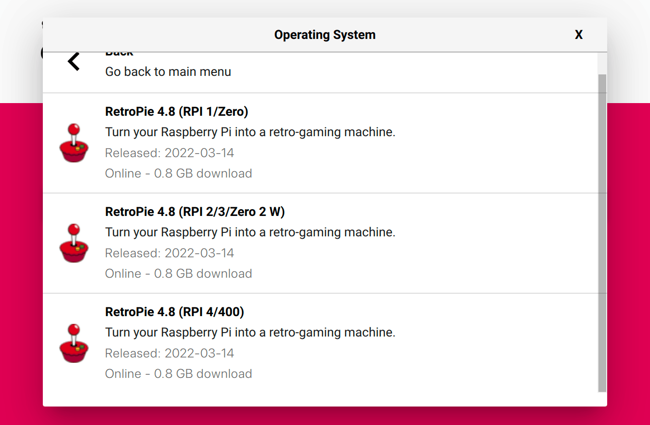
- Choose the version of RetroPie that corresponds to your specific board.
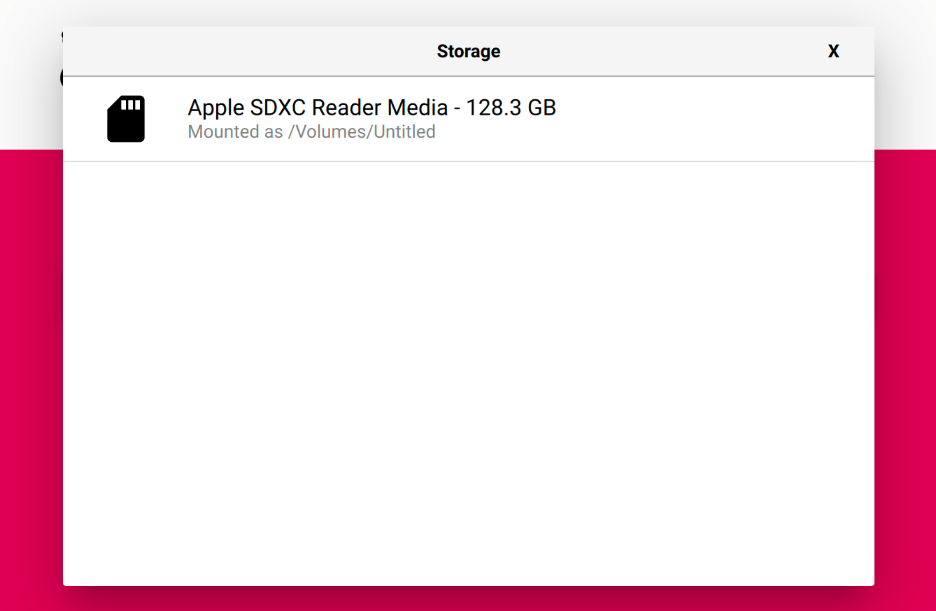
- Click Choose storage and select your SD card on the list to install RetroPie into it.
- Click Next and install RetroPie on the SD card.
- Now you can install games. I wrote an in-depth guide about installing games in RetroPie. You can always check RetroPie's official documentation for more details.
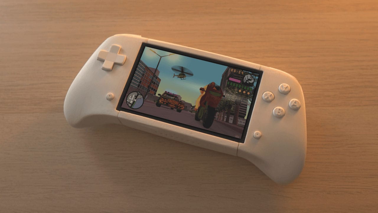
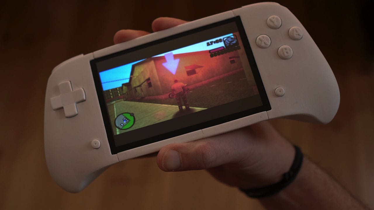
02. Screen
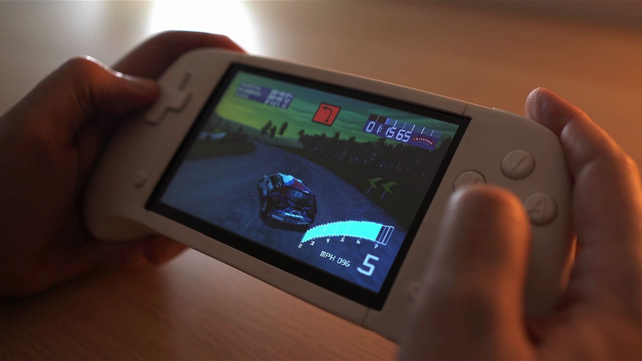
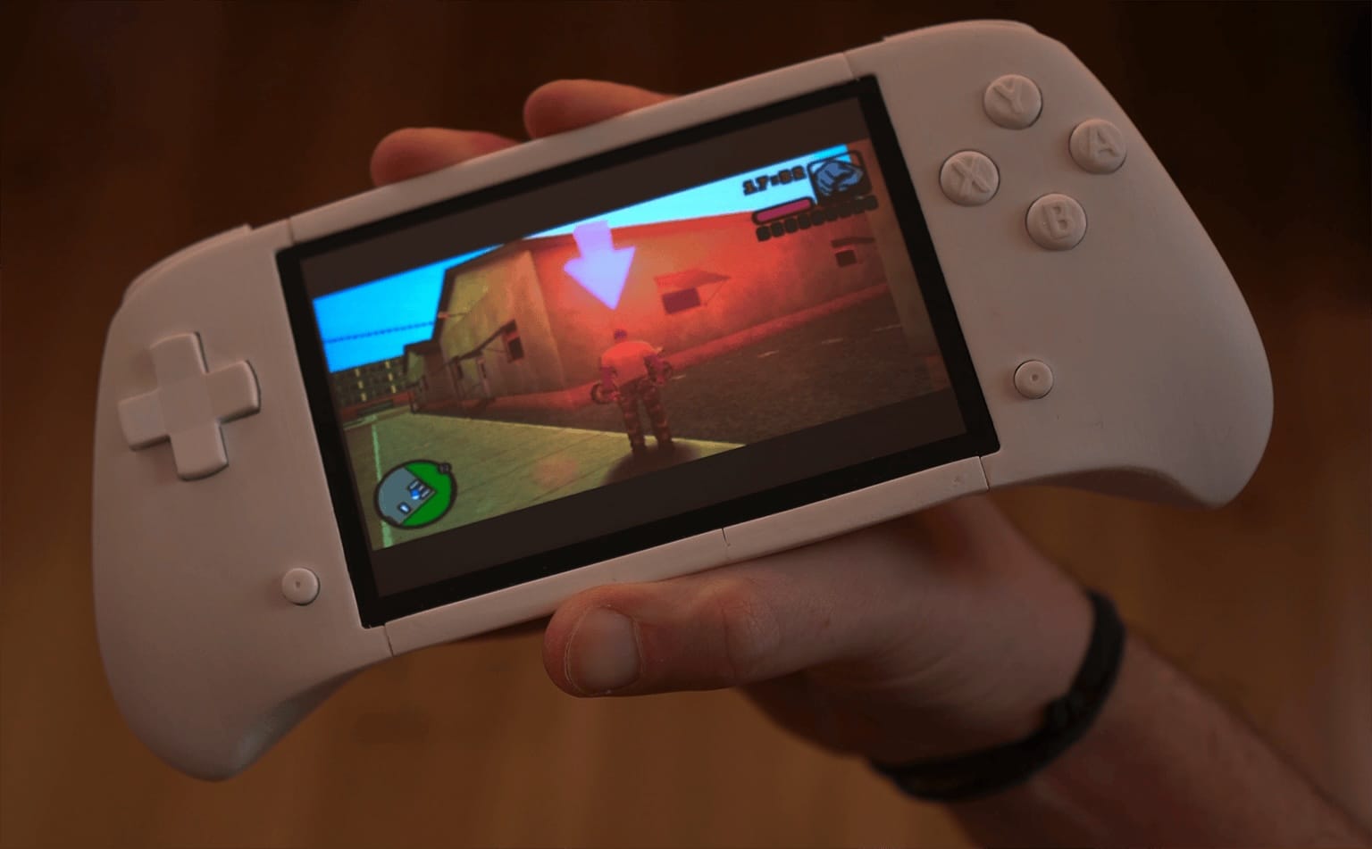
I've chosen a 5-inch screen because, in my opinion, the size went better with the case that I wanted to design. I knew that I wanted to use a normal console controller as a reference, and add a screen that fell like it was part of the design.
A counterexample for me was the PlayStation Portal, which is literally a PS5 controller cut in half and glued to the sides of a tablet. I didn't want that:
Aspect ratio: For this project I went for a screen with 5:3 ratio which is similar to the 4:3 aspect ratio in old TVs. I wanted this console to be mostly a retro game machine. The 5:3 ratio is also good for running the newest games in 16:9 with minimal horizontal black bars.
Resolution: 800x480 looks great for the size, although I wouldn't accept less than that resolution and I would definitely go higher if the price doesn't jump abruptly on a better model.
Audio
For projects like this I always think about audio as part of the display because HDMI is a standard for audio/video interface. The display that I've used came with an integrated speaker that made this build easier.
That was the approach I chose for my implementation. In case you want to adapt the design to have speakers, the second best option that I recommend to you is to consider speakers that were designed for portable screens. For example this one, although you will need to make sure you have the space needed inside your case.
Step 2. Connect it to a TV/monitor and keyboard.
- Using HDMI, connect the board to any TV, computer monitor, or the display I specified.
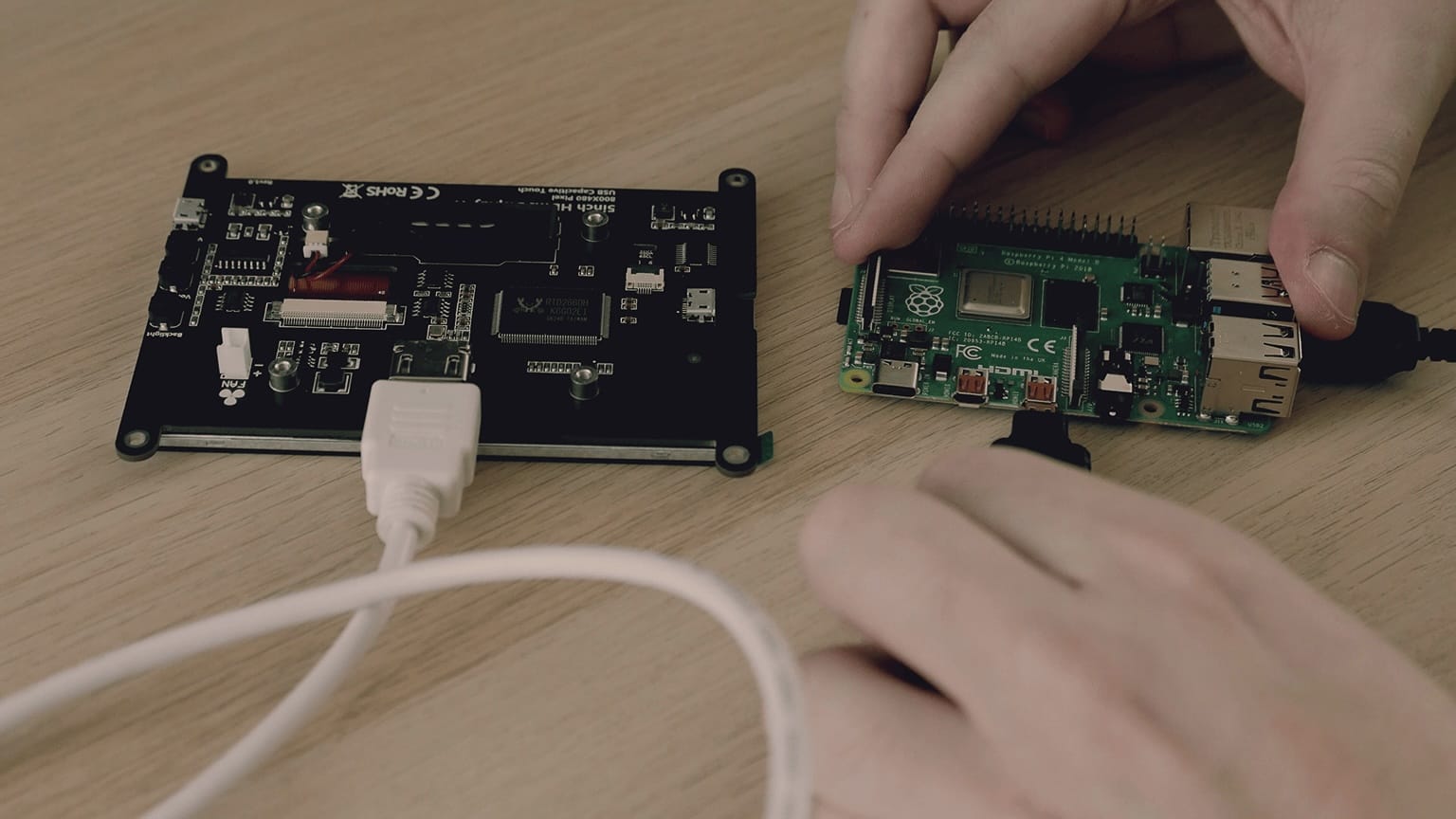
- Connect a keyboard.
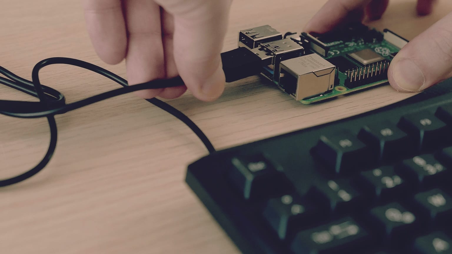
- Connect the Raspberry Pi to a power supply.
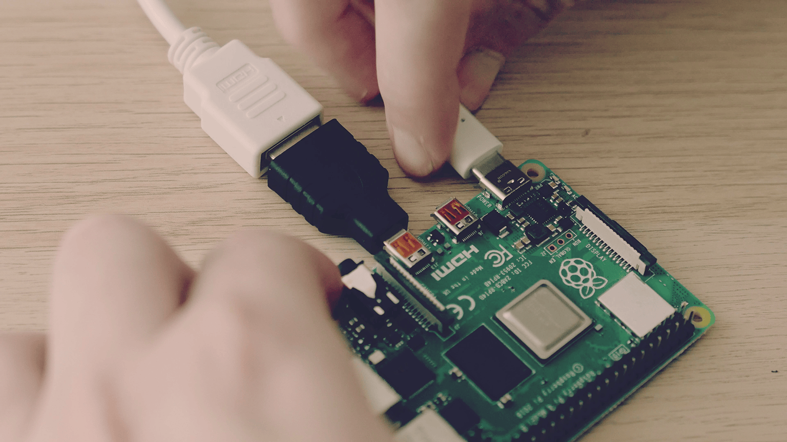
- Turn on the Raspberry Pi.
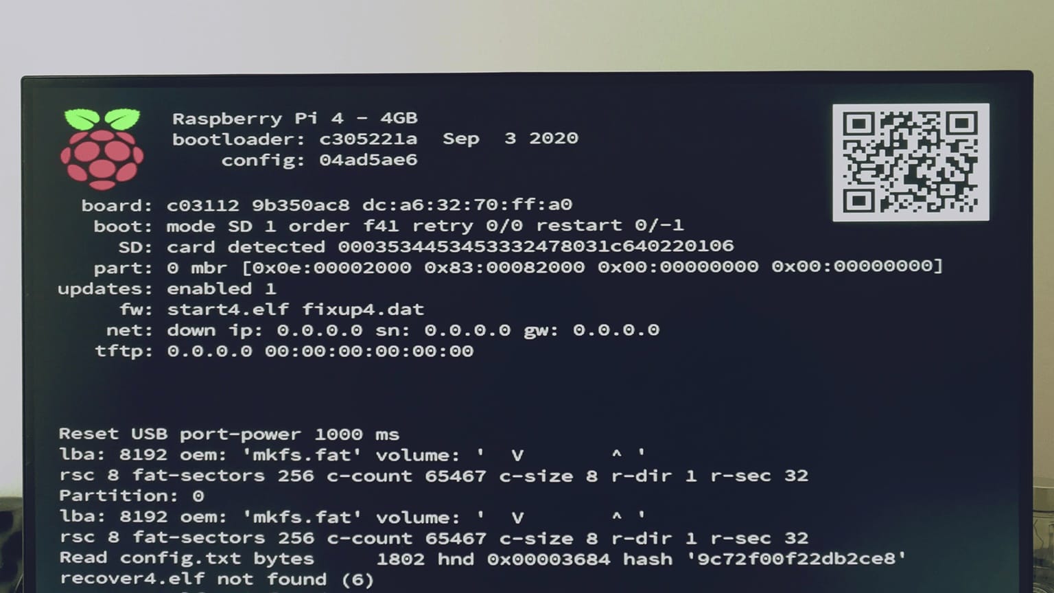
- Configure the buttons: The first time you enter RetroPie it will ask you to set up all your buttons. Use your keyboard to assign the keys you want. You can enter the same menu later using START Configure Input.
These are the keys I set up:
- D-PAD UP Key W
- D-PAD DOWN Key S
- D-PAD LEFT Key A
- D-PAD RIGHT Key D
- START Key Return (Enter)
- SELECT Key Right Shift
- BUTTON A / EAST Key H
- BUTTON B / SOUTH Key G
- BUTTON X / NORTH Key T
- BUTTON Y / WEST Key F
- LEFT SHOULDER Key Q
- RIGHT SHOULDER Key E
- LEFT TRIGGER Key Z
- RIGHT TRIGGER Key C
- HOTKEY ENABLE Key Right Shift (same as SELECT)
You'll also need to use all those keys to navigate RetroPie's interface. For example, use the D-PAD keys to move through the menus and A / EAST to confirm.
The button you set as HOTKEY ENABLE can be any button previously used (I highly recommend using SELECT). The hotkey used in combo with another button gives you a set of tools while in a game:
- Exit game: SELECT + START
- Reset game: SELECT + B / SOUTH
- Open RetroArch menu: SELECT + X / NORTH
- Load game state: SELECT + LEFT SHOULDER
- Save game state: SELECT + RIGHT SHOULDER
- Next save slot: SELECT + D-PAD RIGHT
- Previous save slot: SELECT + D-PAD LEFT
You can set up more hotkey combos, such as pausing game, taking a screenshot, fast forwarding, rewinding, muting sound, showing FPS, and changing volume. I covered this topic in another blog post.
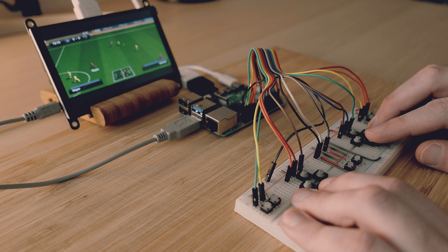
03. Gamepad
The best way to prototype a gamepad and tinker until it works as expected is using a breadboard. In case you don't know what a breadboard is and how to use them, there are plenty of guides that talk about them like this tutorial on Sparkfun.
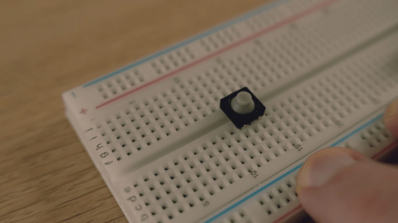
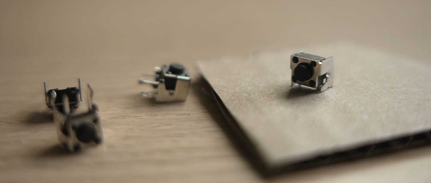
Buttons: For any project that need buttons, there is this standard 6mm tactile switch buttons that are everywhere. The only problem is that they feel super clicky. I found 2 variants that improve how they feel to the touch. These made out of silicone (still clicky but not so much):
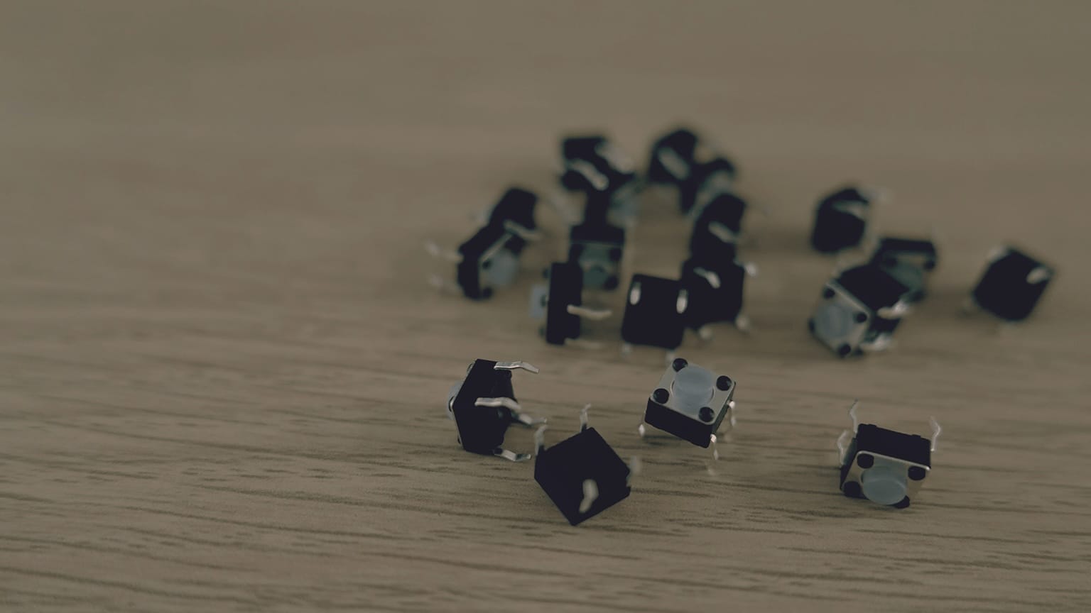
And these ones are very squishy buttons (perfect for emulating that gamepad feeling):
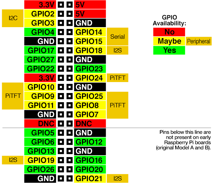
GPIO pins: The Raspberry Pi has 40 pins (except for early models) that can be used for many different things. Any pin in green and yellow here is available to be used as a digital input. That means that you can connect any push button to them to be readed by the board.
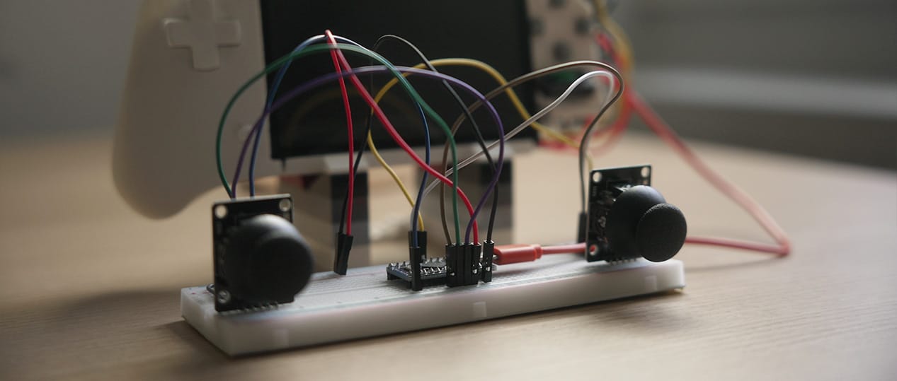
Analog joysticks: For this first prototype I decided not to include analog sticks. The Raspberry Pi doesn't have any analog inputs, so it needs an entire implementation for that. I'm currently working on adding thumb sticks to the next version of the console by adding an Arduino Pro Micro connected via USB.
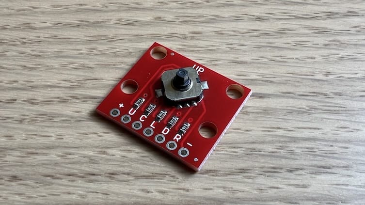
When I started the project, I had the idea to use some "fake" analog sticks. By simply using an 8-way navigation switch I could have read the 8 directions as digital inputs, but I couldn't find any model to buy. I bought a 5-way switch to test it, but as the name implies, it doesn't support moving in diagonal:
Step 3. Add your own custom buttons.
- Add all the tactile buttons to the breadboard and wire one of the legs to the ground row (-) of the board.
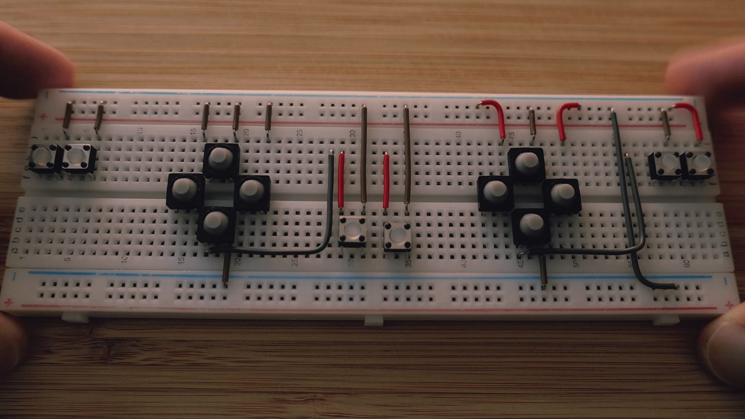
- Connect the other leg of the buttons (+) to a pin on the Rasbperry Pi using jumper wires. You can connect any button to any available pin but it's important to take note of which buttons you connect to which pins.
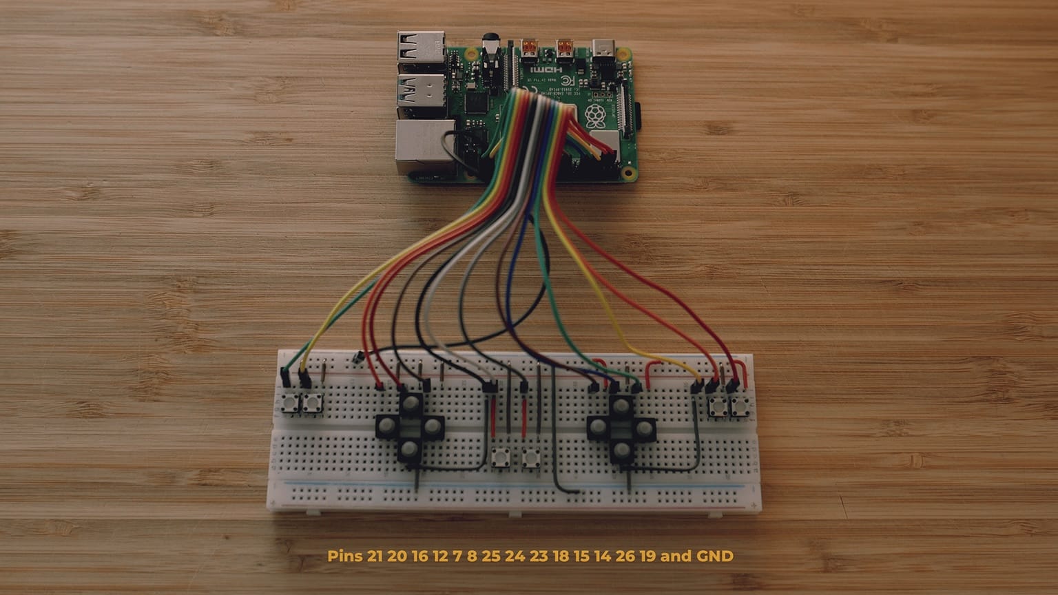
This is the wiring diagram with the pins I used:
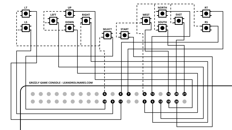
Download wiring diagram here. - Connect to Wi-Fi following the official docs:
RetroPie WIFI Connect to WiFi network - Access the Raspberry Pi command line either locally by pressing F4 while in RetroPie, or remotely by enabling SSH, assigning a static IP, and running on your computer:
$ ssh pi@192.168.X.X - Install the Adafruit-Retrogame utility, which enables you to map the GPIO pins to work as a virtual keyboard. From the Raspberry Pi's command line, download Adafruit's script file retrogame.sh and execute it:
You will be prompted to select a configuration. Choose any option and follow the steps to reboot.$ curl https://raw.githubusercontent.com/adafruit/Raspberry-Pi-Installer-Scripts/master/retrogame.sh > retrogame.sh $ sudo bash retrogame.sh - After rebooting, access the command line again and edit the retrogame.cfg file to map the GPIO pins to the keys you configured in step 2:
Here's an example of my retrogame.cfg file where I map my keyboard keys to my GPIO pins:$ sudo nano /boot/retrogame.cfg
For a list of all the possible key IDs take a look at Retrogame's keyTable.h file.# Key GPIO Pin Console Button W 19 # D-PAD UP S 5 # D-PAD DOWN A 13 # D-PAD LEFT D 6 # D-PAD RIGHT ENTER 26 # START RIGHTSHIFT 10 # SELECT H 20 # BUTTON A / EAST G 21 # BUTTON B / SOUTH T 12 # BUTTON X / NORTH F 16 # BUTTON Y / WEST Q 9 # LEFT SHOULDER E 8 # RIGHT SHOULDER Z 11 # LEFT TRIGGER C 7 # RIGHT TRIGGER - Save the changes and exit Nano. You can do both at the same time by pressing ctrl + X.
- Reboot the console and check that everything works as expected.
You should be able to navigate the interface, start games, and play them using your custom gamepad.$ sudo reboot
04. Power supply
There are plenty of ways to power a Raspberry Pi without pluging it into a wall. The model 4 that I used has a USB-C port that needs 5V 3A to work (older boards need less amperage). This means that you could power this project with, for example, a simple power bank. There is also plenty of HATs that allow you to add power from an external battery.
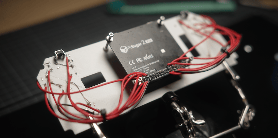
I decided to go with the PiSugar 2 Pro specifically for its features. There were many version of that same model after I got it, like the PiSugar 2 Plus, S Plus, and 3 Plus. All of them have the same footprint, therefore they should be compatible with this build. The important thing is to get the one with the 5000 mAh battery since this console needs a lot of power.
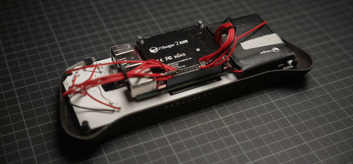
The PiSugar is a UPS (Uninterruptible Power Supply). It's a device that provides near-instantaneous backup electric power to the board when the input power source or main power "fails". It maintains the operation uninterrupted, and safely shut down when the power is too low.
The PiSugar connects via pogo pins. Unlike other HATs, it sits on the back of the Rasbperry Pi, making it almost imperceptible. The sad thing was that I needed to transform the PiSugar into a normal HAT because the connectors that hold the Raspberry Pi attached to the display (HDMI and USB) don't allow to have anything between them.
Batteries: Any lithium-ion battery with at least 2500mAh should be enough to power a Raspberry Pi handheld game console. The PiSugar came with 5000mAh, and they claim the battery life is 8-10 hours. For me it's been around half that time in total when making the Rasbperry Pi work at its maximum, emulating console games, and with the fan turned on 100% of the time.
Step 4. Install the UPS and battery.
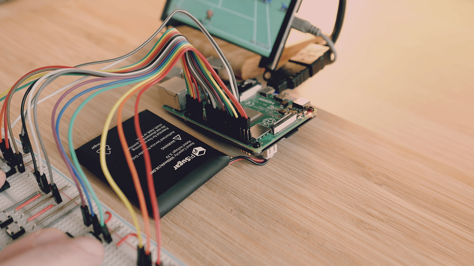
Before anything, check that the PiSugar is working properly by connecting it to the Raspberry Pi according to their instructions. At this point, you'll already have a wireless game console!
The next steps involve converting the PiSugar from Hardware Under Board (HUB) to Hardware Attached on Top (HAT) so that it fits in the case. I recommend only attempting this if you are experienced with electronics.
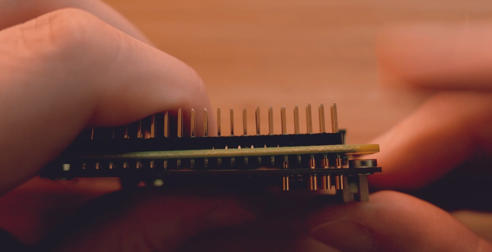
- Carefully remove the pogo pins (the golden cylindrical connectors) from the PiSugar. Pull out the side that is not spring-loaded (the rigid side) straight out. You may need to twist the pin slightly to help it come out.
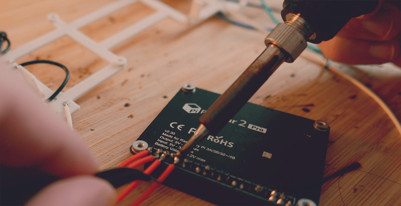
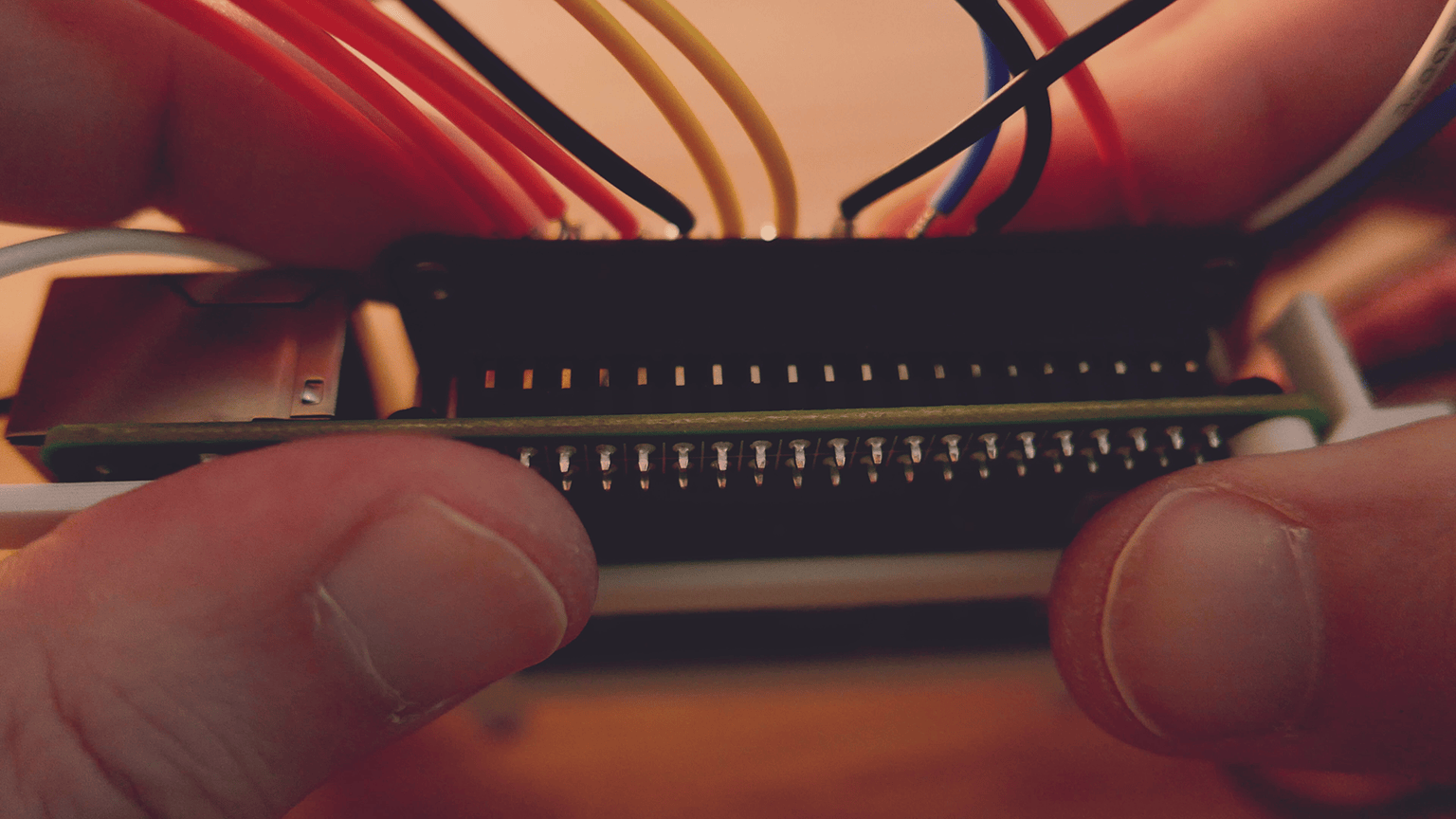
- Solder a 2x20-pins female GPIO header to the PiSugar. Be sure to solder at least the pins where the pogo pins were so the PiSugar can function properly. Consider using flux to make the soldering process easier.
- Solder wires to the GPIO pins you will use for the buttons (the ones you set up in step 3).
- Connect the battery to the PiSugar and attach the PiSugar to the Raspberry Pi for a test.
- Turn on the Rasbperry Pi and disconnect it from power to make sure it works wirelessly.
05. Circuitry
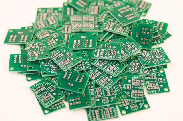
When it comes to taking a prototype from the breadboard to the next level, there are plenty of options. The one that would make more sense for this project is designing a custom PCB. However there are other methods that allow for quicker prototyping.
Printed Circuit Board
A PCB is a board that holds all the electronic components needed for a device to work. For example, the Raspberry Pi's green board is a PCB. Same with PiSugar's black board. Every electronic device has one inside, and you can design your own to suit your own needs. There are services that print the board for you like JLCPCB or PCBWay among others. The quality is great for a low price.
For me the only problem with this approach is that the process of iterating is slow. I needed to remove as much bottlenecks as possible for a first prototype. I'll eventually design my own custom PCB, but I needed to understand the place for each component first. For example, I'm currently working on fixing some flaws in the shoulder buttons and it means that I potentially need to move the battery around.
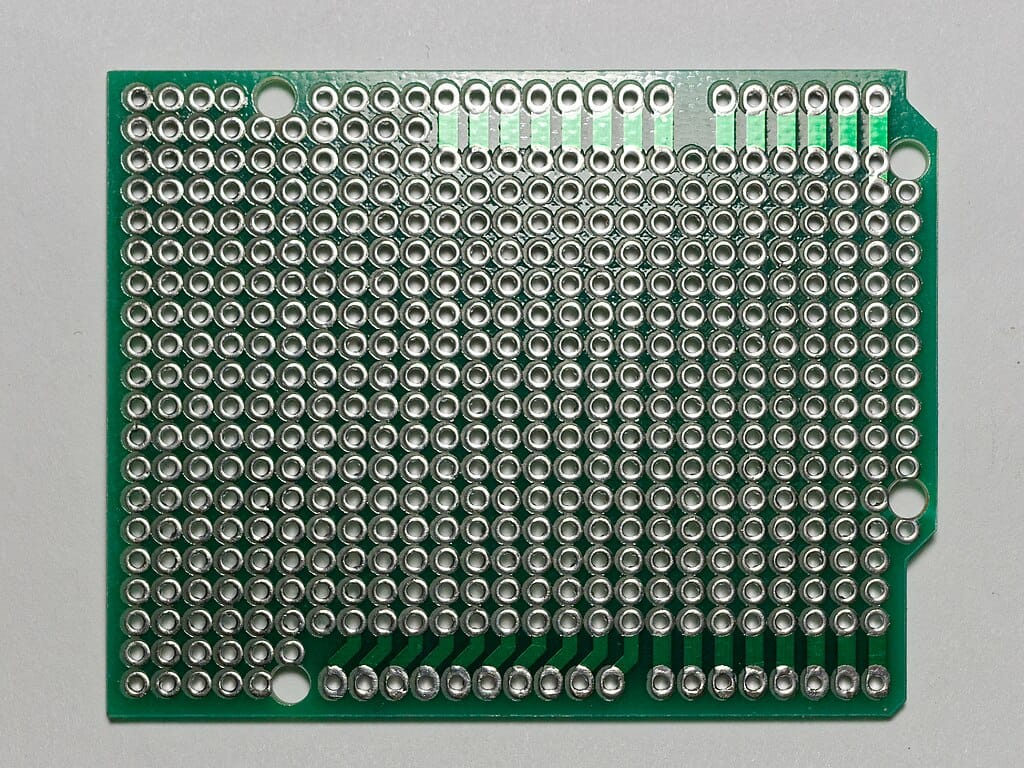
Perfboard
Perfboards are boards that are pre-drilled in a grid disposition. It allows you to insert the electronic components on the designated places, as in a breadboard, and solder them to the board. This is like a step in the middle between a breadboard and a custom PCB. The problem for me is that I'm forced to place each push button on a very specific spot. I wanted to have 100% freedom of placing the buttons wherever the design would make it more visually attractive. I've seen plenty of consoles using perfboards, and the thing I don't like is how the design adapts to where the components need to be placed. I wanted that to be the exact opposite. The desing must dictate where the components will be placed, not the other way around.
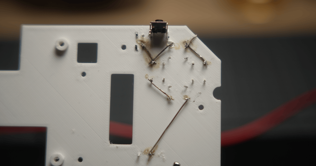
3D-printed board
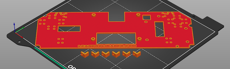
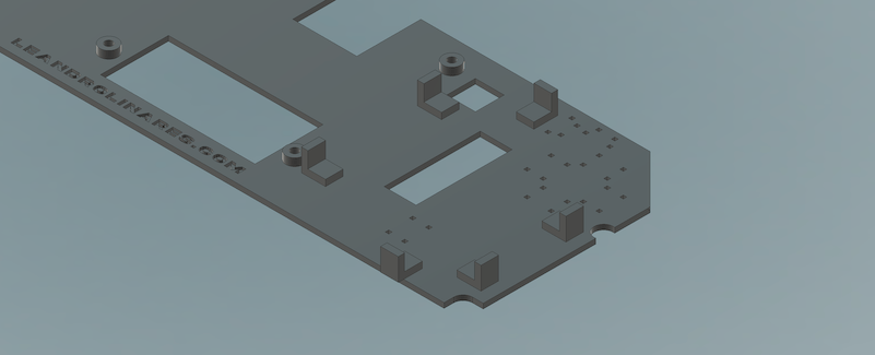
I wouldn't recommend using a 3D printed board to hold electronics that can raise temperature or that need to do things with electric currents. Since I only needed to hold tactile push buttons, I decided give this technique a try. The main advantage of doing it this way is that it's an ultra fast way of prototyping a board.
There is another advantage: you can work with crazy shapes, like I did with the parts that hold the shoulder buttons or where I inserted the fan. The problem is, I'm limiting the people who build this console to 3D print the board just because of those unique shapes. What I learned in the process is that by using the right components for the right circumstances I'll be able to design a proper standard PCB. For example, I've switched to use 90-degree tactile buttons for the shoulders and triggers.
Step 5. Wire and assemble.
- Read the license and download the STL files.
- Print the pcb-prototype and 6 battery-bracket in PETG with 0.15mm layers and 15% infill. Print the brackets to their side and with supports. If you need to print the pcb at 45 degrees, as in the picture, make sure to set the fill angle to 0 in the slicer.
- Attach the 6 battery brackets to the main piece with super glue.
- Insert the push buttons into the frame. Put 4 90-degree buttons on the shoulders and triggers, and 10 normal buttons on the rest. The buttons should stay tight-ish in place. If that's not the case, reprint the piece playing around with the layers thickness on the slicer.
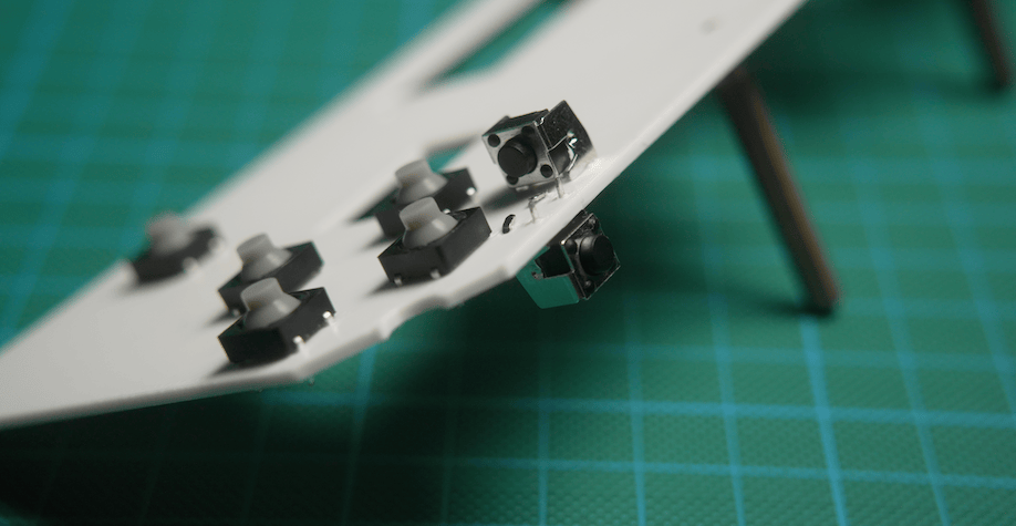
- Solder one leg (-) of each button in series, connecting all of them together.
- Solder the opposite leg (+) of each button to a GPIO pin on the PiSugar header. Make sure you connect them to the same pins you chose on step 3.
- Attach the Raspberry Pi to the PCB-prototype using two screws on the pins side and two 10mm spacers on the other side.
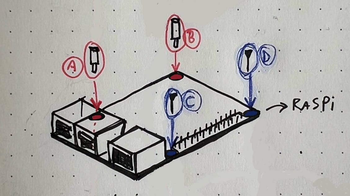
(A) and (B) are the 10mm spacers. (C) and (D) are the screws. - Connect the PiSugar to the Raspberry Pi and secure it to the spacers using 2 screws. Be sure to connect the battery to the PiSugar first, as there will very little space for the battery wires to fit.
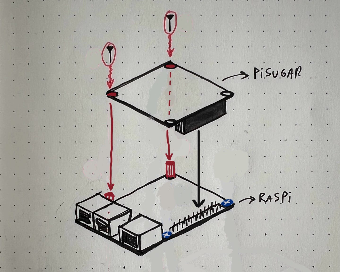
The screws fasten the PiSugar to the spacers. - Connect the Raspberry Pi to the display. Any screen will need to get power from USB and video/audio through HDMI. I'm using these PCB-based connectors that came with the display:

The second best option are ribbon cables, also found as band or flat cables.
06. Case
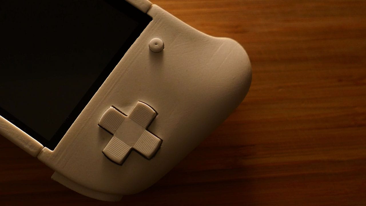
Designing my own case took me a very long time. It wasn't time spent only on planning and execution, but also the compound results of uncountable years of dissasembling gamepads to repair them noting how every piece works. I'll try to point the main things I had in mind while designing this console.

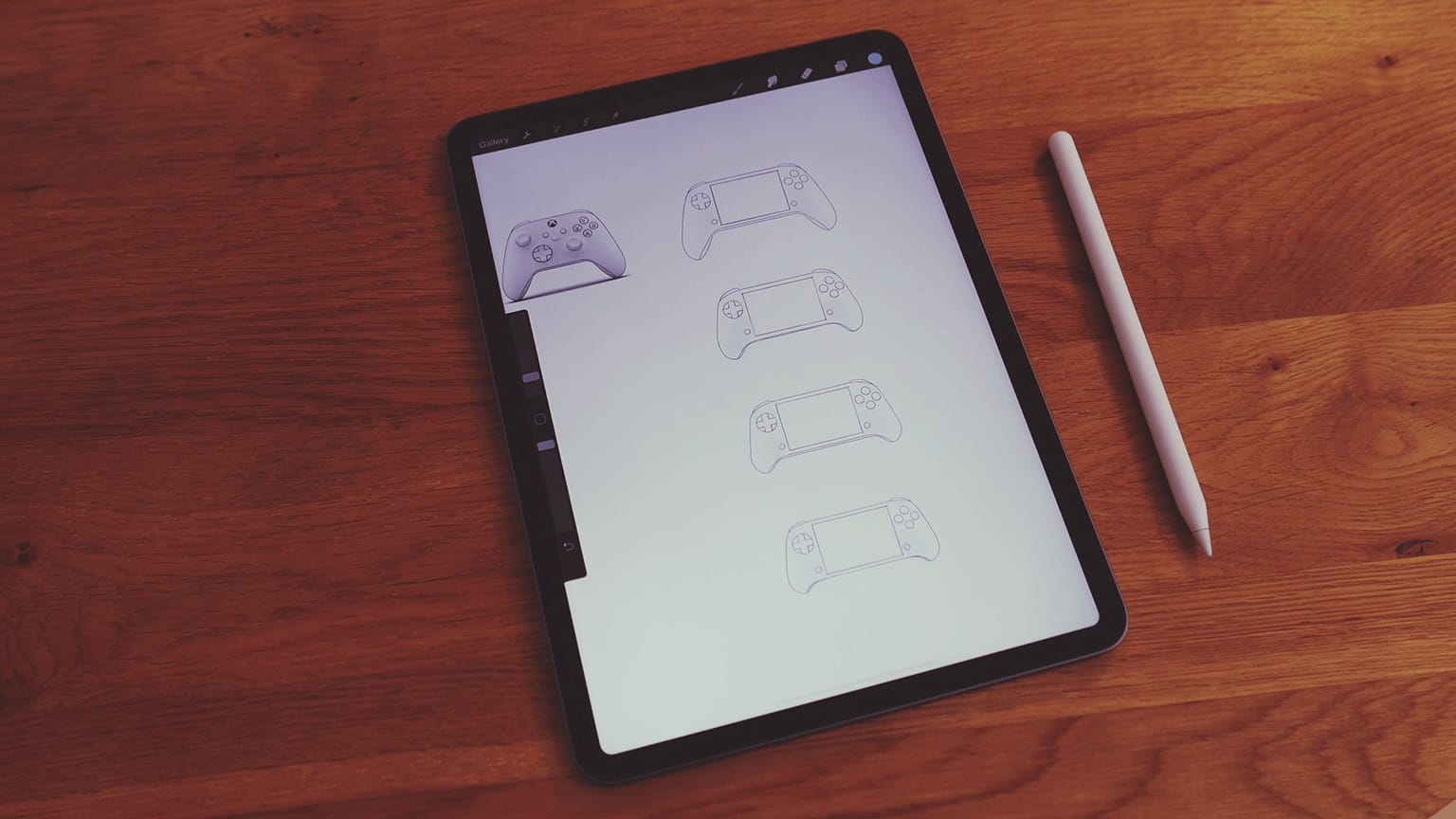
I started drawing 4 different versions with slightly different dimensions on Procreate for iPad. I already had all the components in hand so I already knew that the size of the screen and the depth of all the things were a constant. I made tiny changes in the position of the d-pad, the other buttons, and the length of the handles. The idea was to see which one looked more natural.
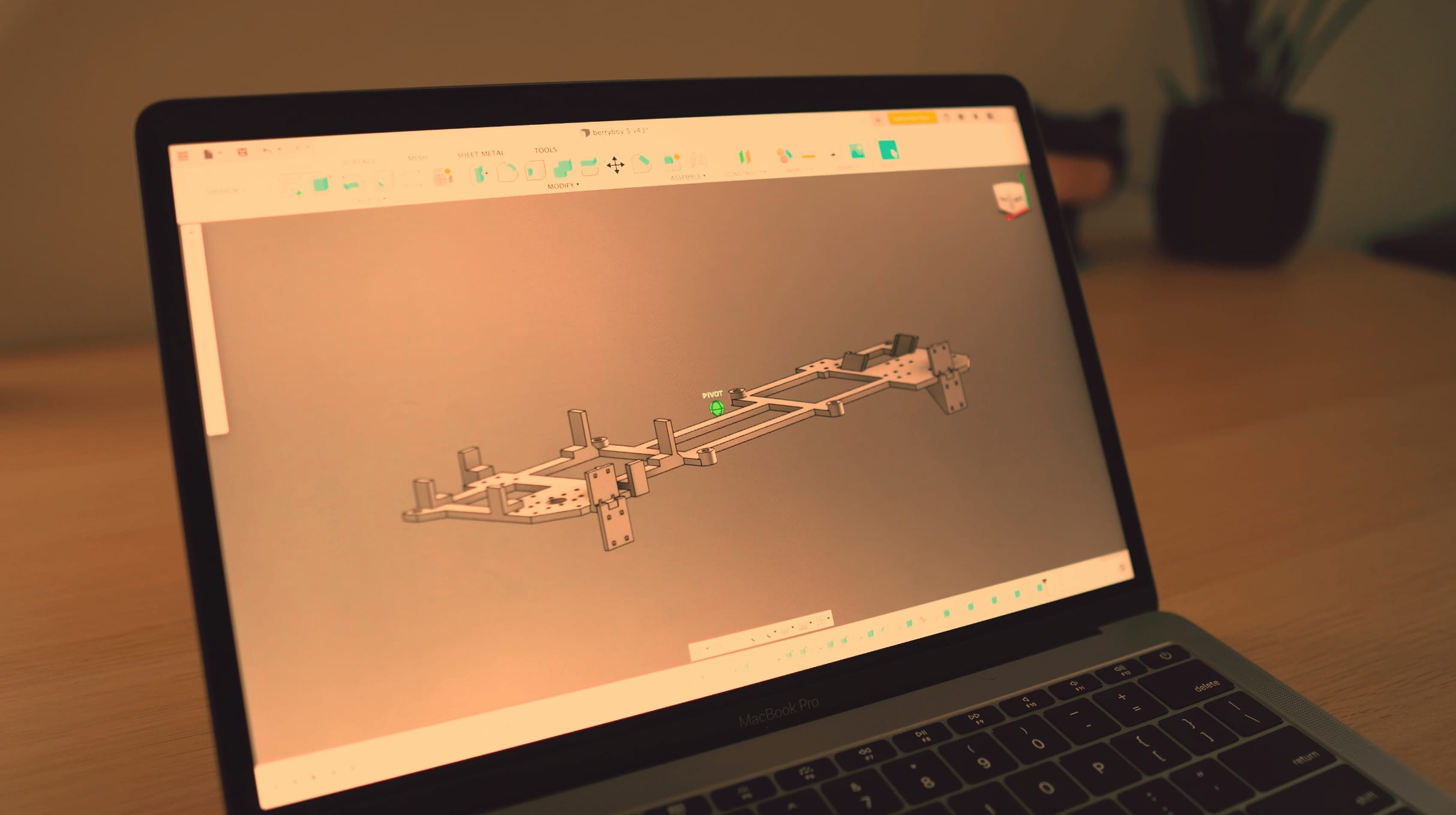
I modeled the console out of a rectangular box using t-splines in Autodesk Fusion 360. I basically defined one of the halves as a mirror of the other one (the green line on the screenshot) and started pulling its vectors until I got the shape I was looking for.
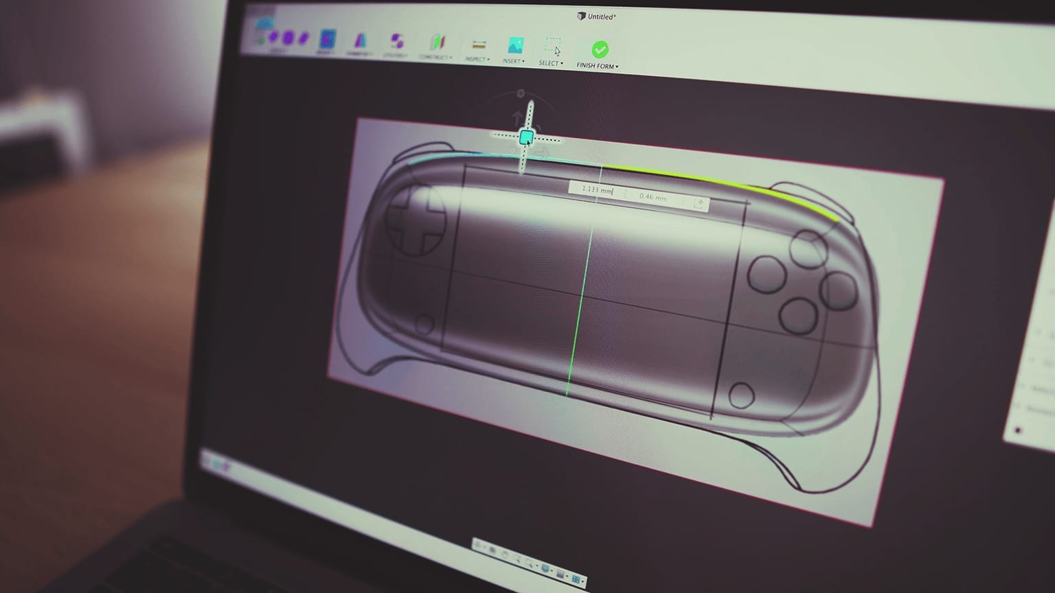
It took several iterations to get it right. One thing is drawing something on the screen and another different thing is to have it in its physical form. Also, 3d printing has its own set of constraints that you need to respect.
I printed all the prototypes in PLA to be able to iterate fast, but I used PETG to print the final product. This was actually a mistake. PETG ended up being an extremely soft material, so sanding it didn't result on a smooth surface. The reason I printed it in PETG was because I feared that the console could reach temperatures high enough to soften PLA. It turns out that that's not the case and I'm even working on the posibility of removing the active cooling system.
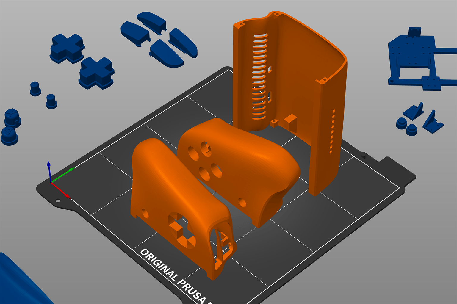
Since 3d printing is a different manufacture process than, for example, mold casting, it allows for different ways of assembly. Instead of the tradicional cut in half of any game console or gamepad, I made 3 different parts. The main reason was to being able to print it on my Prusa Mini.
I like that the components are assembled from the sides instead of from the back. Though, I later switched to having front and back sides like any traditional gamepad.
Step 6. Build an enclosure.
- Read the license and download the STL files.
-
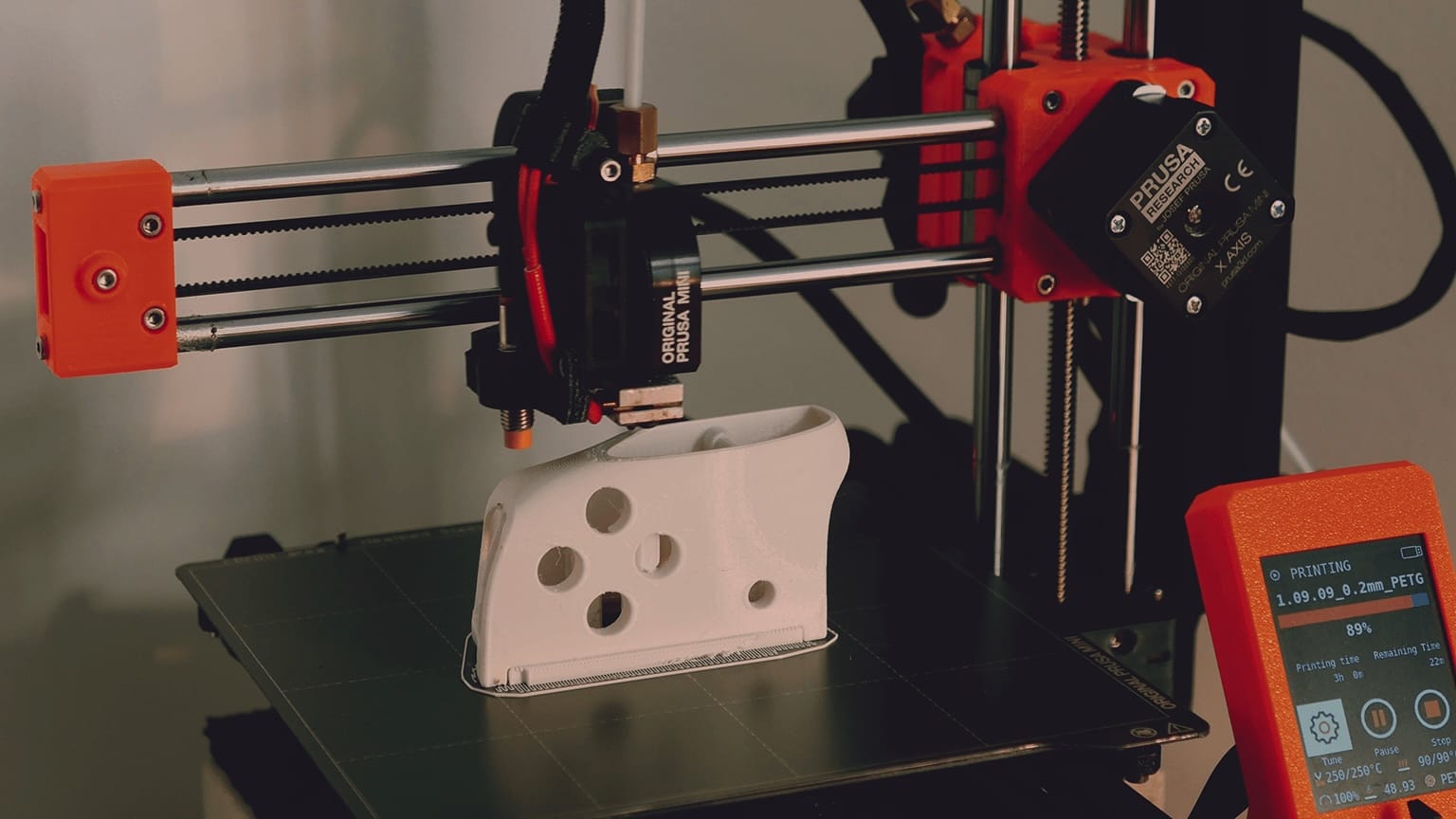
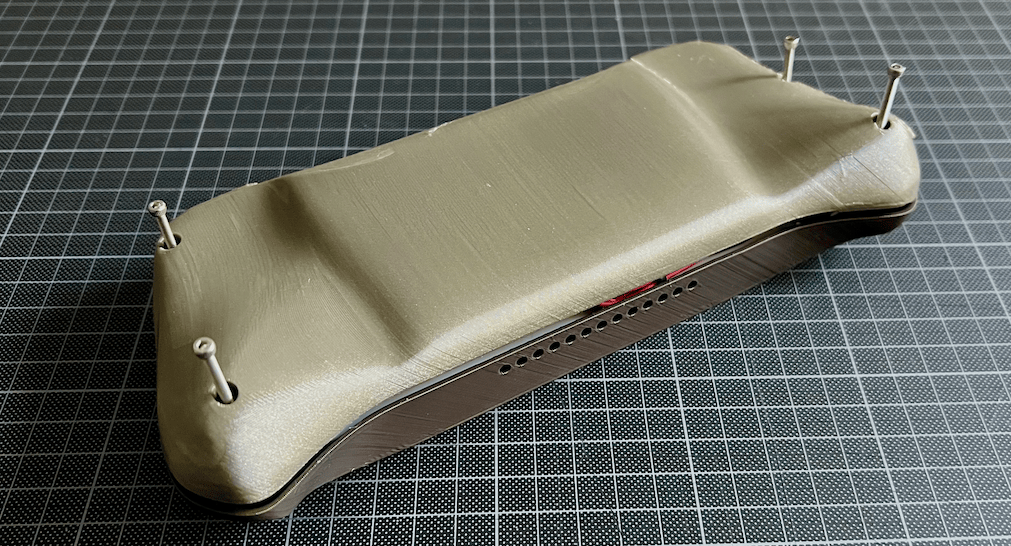
Print the case-front and case-back in PLA. What worked best for me for strength and speed was printing them at 45 degrees, with custom support enforcers where needed (ensure nothing hangs unsupported in mid-air), and organic supports:
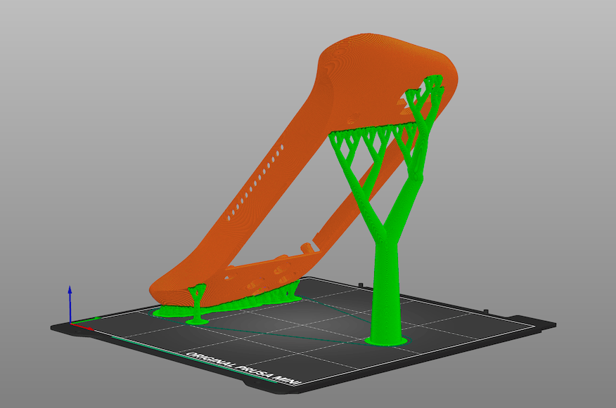
Front case ☝️ Around 4hs printing on Prusa Mini with 0.25mm layers. 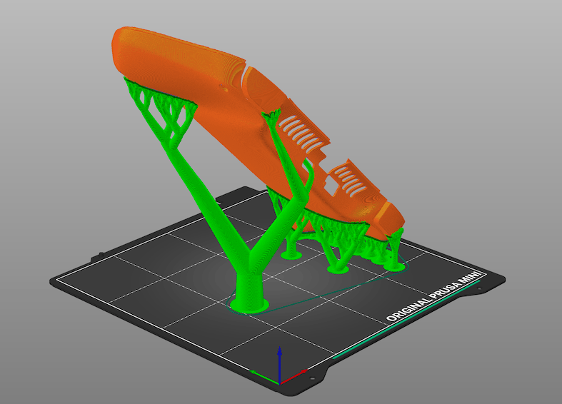
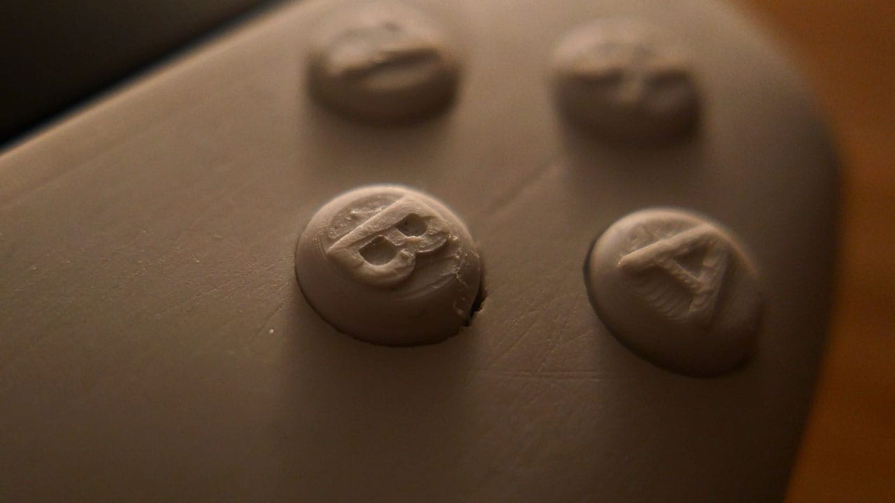
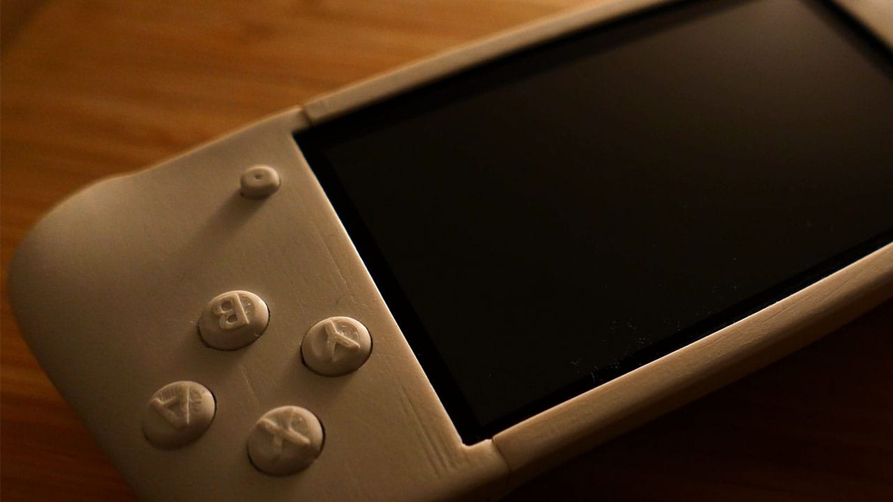
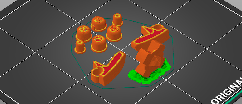
Back case ☝️ Around 6hs printing on Prusa Mini with 0.25mm layers. - Print all the buttons together in PLA, ensuring layer height is 0.10mm or less. I recommend printing the d-pad on its side with some supports:
- Insert the buttons into the front case.
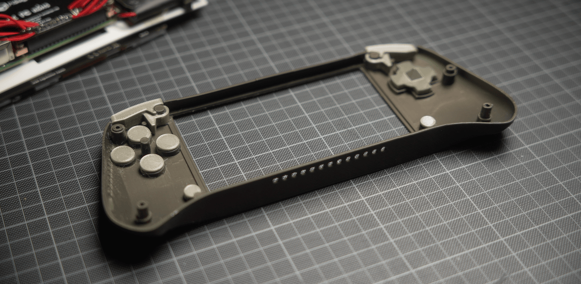
- Place the assembled components inside. At this point you'll need to cut the 4 mounting holes that stick out of the display. That process is irreversible.
- Attach the back case and secure everything with M2.5 screws. Ideally, use 16mm long (⅝ in) screws at the top and 20mm (¾ in) at the bottom.
- Done! Enjoy your own Rasbperry Pi handheld game console.
Wrapup
Let me know how it goes! If you build it, send some pictures. Tell me what problems you found in the process, what you had to improve, what I can improve.
License
This work is licensed under the Creative Commons Attribution-NonCommercial-ShareAlike 4.0 International (CC BY-NC-SA 4.0).
This license enables reusers to distribute, remix, adapt, and build upon the material in any medium or format for noncommercial purposes only, and only so long as attribution is given to the creator. If you remix, adapt, or build upon the material, you must license the modified material under identical terms.
- Attribution: Credit must be given to the creator.
- NonCommercial: Only noncommercial uses of the work are permitted.
- ShareAlike: Adaptations must be shared under the same terms.
See the deed and the legal code.
References
- "Designing my own Game Console" video on my YouTube channel.
- Retro Gaming with Raspberry Pi by Adafruit.
- RPi SD cards by Embedded Linux Wiki.
- RetroPie Official Documentation.
- Raspberry Pi Imager by Raspberry Pi.
- Remote access by Raspberry Pi.
- Raspberry-Pi-Installer-Scripts by Adafruit.
- Adafruit-Retrogame by Adafruit.